

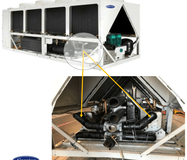
Free production of domestic hot water in chillers with recovery in hotel facilities
Domestic hot water (ACS) is essential for the development of the activity in the hotel facilities.
Its production has been carried out historically and is still maintained, through boilers that use fossil fuels.
Lately, thermal heat pumps are beginning to be used, which in some cases has certain limitations and require a higher investment and a larger volume of storage.
Thermal heat pumps extract energy from the outside (air, water, terrain) and for this they need electrical auxiliary energy, which uses a part of fossil fuels in their production.
In a refrigeration process, to get cold you have to dissipate heat.
In a conventional cooler, that heat is dissipated outside and no utility is obtained from it.
If an additional exchanger is incorporated into a conventional chiller, it becomes a recovery chiller that allows the use of that heat to be used in any process.
- domestic hot water production
- Pool heating
- Spa warming
- Jacuzzi heating
- etc. etc.
In addition, with the advantage that being a heat obtained without energy consumption, it can be used without any regulatory restriction, even in outdoor pools.
A large part of the production of ACS in a hotel facility can be obtained completely free of charge through chillers with recovery.
It is an ecological, efficient and sustainable solution, which considerably reduces the use of fossil fuels, which entails emissions from polluting and greenhouse gases, significantly reducing the environmental impact and the energy bill.
It represents a very important savings in the hotel operation.
Its integration into any ACS production system is relatively simple.
What is a recovery chiller?
A recovery chiller is a conventional chiller to which a heat exchanger is added to recover heat.
Therefore, at the manufacturers level, it is an optional that is incorporated into a standard machine.
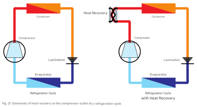
Technical Guide Sanitary Hot Water Central (p. 35)
On the left is a normal refrigeration cycle:
- Evaporator
- Compressor
- Condenser
- Expansion valve (indicated in the figure as lamination)
On the right, a refrigerated cycle with heat recovery is represented:
- An exchanger is installed between the compressor output and the input to the condenser, indicated in the diagram as “heat recovery”
The refrigeration cycle is analyzed in the article published in the We Resolve pages called ‘Energy Optimization Refrigeration Production in Hotel Facilities’, in which it is exposed as is the operation of a chiller.
Everything indicated is applicable, because the only difference is the integration of the heat recoverer.
What heat is possible to recover from a chiller?
a part of the dissipated heat power, or the whole.
- Partial Load Retrievers
- Full Load Retrievers
The most common and that represent a relatively small investment, with a rapid amortization, are the partial load ones, which in most cases are sufficient to meet the needs of the hotel.
Those of total load are justified only if there is a very high demand for thermal energy, they have a much higher cost and their integration is more complex.
How many recoverers are installed per machine?
The chillers are made up of one or more refrigeration circuits.
The usual thing is that they are equipped with two refrigeration circuits.
In each refrigeration circuit, a single recuperator is installed.
Therefore, in a machine with two refrigeration circuits, two recoverers can be installed.
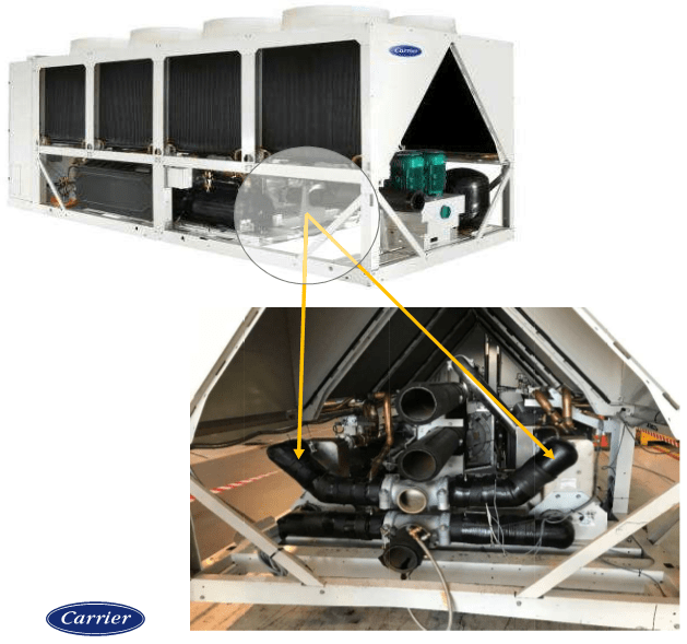
Heat recuperators location
At the bottom of the chiller, the recovery exchangers (in this case two) are displayed under the condensing batteries.
Heat recovery scheme
It is considered an air-water machine with two refrigeration circuits.
the number of Compressors of each circuit (represented by 2) can be variable.
For example, two compressors can go in one circuit and three in another.
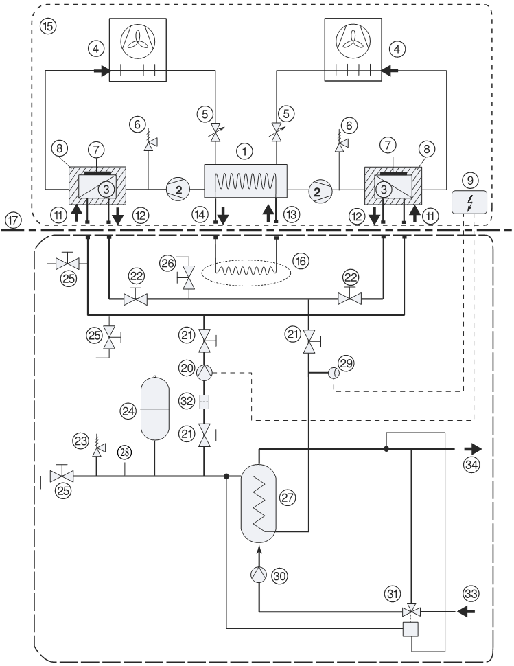
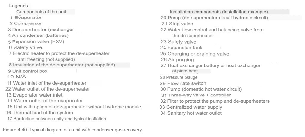
Page 146 Technical Guide “Saving and recovery of energy in air conditioning facilities”
In this scheme, two parts must be distinguished:
- of the line 17 Upwards, the chiller is represented.
- of the line 17 Down the installation is represented.
In this case, the RECOVERY (3) is in series with the set of Compressors (2) and the Capacitor (4).
Integration of the chiller with recovery in the domestic hot water production circuit
To integrate heat recovery into the domestic hot water production circuit, it is necessary to:
Meet the manufacturer’s requirements for:
- Take advantage of the heat produced, optimizing the energy contribution.
- Regulate the flows of water that cross the recoverers of the machines
- If two compressors and three compressors affect in a recuperator, the flows will be different.
- Regulate the flows of water that cross the recoverers of the machines
- prevent serious pathologies from occurring.
- setting a range of operating temperatures.
Comply with the requirements of the regulations for thermal installations, in force in each country.
- Establish expansion systems that are capable of absorbing the overpressures that cause the heating of water.
- Security systems that prevent overpressure from causing:
- accidents due to breakage of pipes or elements.
- deformations of the exchangers.
- Temperature control systems
- three-way valve
- FILTERS
- Proper pumping systems
- Flow switches.
- purgers.
- Filling systems.
- valves.
- etc. etc.
Heat energy production in the compression cycle
The refrigeration process is analyzed in a summarized way in an air-water chiller with two refrigeration circuits.
Air is used to condense the coolant.
Water is used as a heat transfer fluid for distribution to fancoils and air conditioners.
They are independent circuits, which bring cold to the evaporator 1.
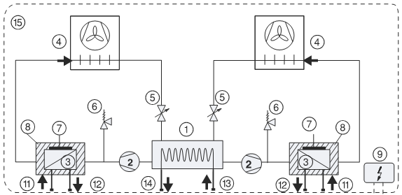
Cooling scheme with recovery
- The evaporator 1 (13 and 14) arrows correspond to the input and output corresponding to the cold water for distribution to fancoils and air conditioners.
- the arrows of the Recovery exchangers (3), Numbered as (11 and 12) correspond to the inlet and outlet of hot water used in heat production.
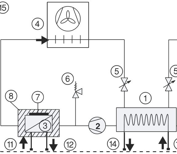
Refrigeration circuit diagram
- Evaporator
- Compressor (or set of compressors)
- Recovery exchanger
- Condenser
- expansion valve
A conventional chiller would be exactly the same without the recuperator (3).
In a conventional chiller the operation is as follows:
- evaporator (1)
- The refrigerant comes out in the form of gas.
- Compressor (2)
- The refrigerant gas is compressed.
- When compressing the gas, it leaves the compressor at high pressure and high temperature.
- As indicated, there may be one or more compressors.
- RECOVERY (3)
- It does not exist in a conventional chiller.
- Capacitor (4)
- Gas from the compressor enters the condenser at high pressure and high temperature.
- A current of air is passed through the condenser batteries at room temperature that dissipates heat outside.
- Along the condenser there is a change of state by passing the gas to liquid.
- Expansion valve (5)
- When passing the refrigerant in the form of a hot liquid, the expansion valve enters the low pressure sector.
- Reducing the pressure evaporates a part of the refrigerant.
- This evaporation cools the remaining liquid.
- evaporator (1)
- The cold liquid enters the evaporator.
- Exchange heat with water from fancoils and air conditioners.
- In the evaporator battery there is a change of state, in which all the liquid passes to gas.
In a compression cycle for a chiller, the primary goal is to produce cold water.
It is observed that for produce cold in evaporator (1), is accurate Dissipate heat in condenser (4).
The heat energy that is obtained in the condensation process is launched into the atmosphere and is not used.
Capture of heat energy in a chiller with recovery
For the use of condensation heat, it is necessary to install:

- Recovery exchanger (3)
- It is a cooling-water exchanger
- Refrigerant circulates through the primary circuit in the form of a high-temperature gas from the compressor.
- Water circulates through the secondary circuit from a closed circuit (represented by the input and output arrows).
- Installs at the outlet of the compressor assembly (2)
- It is the point where the refrigerant gas is at a higher temperature.
- In the recuperator (3) a heat exchange occurs.
- The refrigerant that enters in the form of a gas at high temperature gives heat to the secondary circuit (water) that transfers the heat energy to the circuit of use.
- This cools the refrigerant
- Heat the water
- The heat energy provided by the refrigerant is free and can be used both for the production of domestic hot water, and for any other process that needs heating.
- In the Partial Load Retrievers (those that are usually installed to a greater extent) Heat exchange is through sensitive heat. Gas enters at high temperature and the colder gas comes out.
- This gas passes to the condensing battery (4) where the process is completed. leaving this battery in the form of liquid.
- These heat recoverers are named in technical catalogs from the manufacturers of Desuperheater.
- In the Full Load Retrievers (only in special installations) The exchange is sensitive and latent. The refrigerant enters in the form of gas and leaves in the form of a liquid, taking advantage of all the condensation heat.
- If 100% of the heat power is recovered, the condensing battery would not enter (4)
use of heat energy
The use of heat energy occurs only and exclusively when it is necessary to refrigerate.
It is not possible to produce heat, if the chiller is not cold.
Once the heat energy has been captured in the recuperator (3), it is necessary to transmit it to the processes in which heat is required, such as domestic hot water.
It is not admissible to pass directly the water that is intended to be heated (pools or domestic hot water), through the recovering exchanger (3), because its refrigerant circulates through its primary circuit, which cannot be mixed in case of breakage with the water for use.
Is the heat production of a chiller always the same?
No, the heat production in a recovery chiller is not always the same.
It depends on a series of parameters such as:
- outside temperature. (which varies)
- evaporation temperature. (which varies)
- number of compressors that are in operation. (depending on consumption)
If the outside temperature is high, the gases leave the compressor at a higher temperature and the production of heat energy that can be recovered is higher.
If the chiller works at partial load, the energy input is lower and the production of heat energy is also less.
In coastal hotels during the summer season, with high outdoor temperatures and a greater number of hours of operation, the production of hot water is higher and covers a good part of the demand.
Therefore, the production of heat energy, as well as the temperature at which it provides it is totally variable.
In partial recovery chillers, it can be estimated that free hot water production can range from 15% to 30%.
Is it possible to increase the production of hot water?
If possible, setting a condensation control.
The free contribution is made with a chiller operation optimized for cold production.
This assumes that the condensation of the refrigerant will depend on the outside temperature at all times.
Recovery chillers allow the refrigerant to be condensed at a higher temperature, thus increasing the production of hot water, although with an increase in energy consumption.
As long as this increase in energy consumption is less than the cost of hot water production, it would be profitable.
Transfer of heat energy to the production of domestic hot water
The chillers establish connection points for the outside networks.
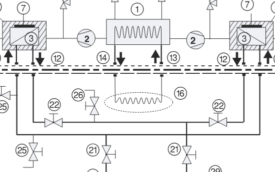
This figure only analyzes
3 Recoverers (hot water connection)
21 Valves Connection Circuit Recovery
The connection of element 1 (evaporator) is for cooling.
The connections of the recuperators (3) have been unified to establish a single recovery circuit.
Valve 21 on the right is the heat drive.
Valve 21 on the left is the heat return.
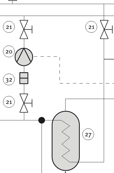
This figure only analyzes
21 Valves Connection Circuit Recovery
27 Water exchanger Water for heating ACS
20 Primary Pump (Heat uptake of the Retrievers)
When hot water is produced in the recuperators (3) the pump (20) is started, which transfers the heat generated in the retrievers from the chiller to the exchanger primary (27).
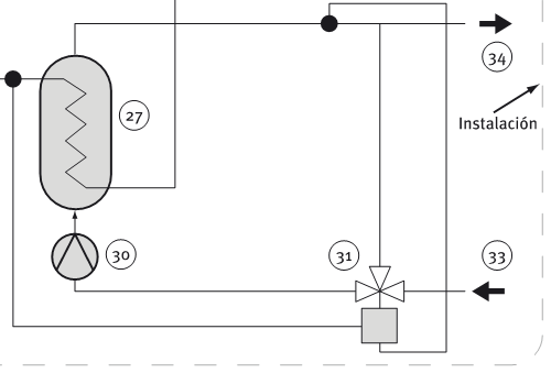
This figure only analyzes
27 Plate exchanger
30 Secondary Pump (Domestic Hot Water Circuit)
33 Domestic hot water inlet (from preheat accumulator)
34 Domestic hot water outlet (to preheat accumulator)
In the exchanger (27) the energy transfer of hot water produced in the chiller (recoverer 3) occurs to the domestic hot water consumption circuit.
The (27) is a water-water exchanger:
- Primary
- Water from the chiller (recoverer 3, powered by pump 20).
- Secondary
- water to be heated, (powered by pump 30).
- Domestic hot water comes from the accumulator or preheat accumulators.
- water to be heated, (powered by pump 30).
domestic hot water production
The accumulator from which the domestic hot water circuit starts must always be at a minimum temperature of 60ºC, to fight the legionella bacteria.
The rest of the accumulators installed in series are considered pre-heating and have no requirements in terms of temperature.
A cooler with recovery only provides hot water if there is a demand for refrigeration and it also does so at variable temperatures.
Therefore, the heat energy it produces, it is always necessary to take it to the accumulator or preheat accumulators.
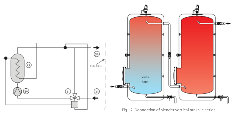
In the figure it is represented.
- Hydraulic connections that would go to the preheating accumulator (left).
- The preheat accumulator (left) is in series with the heating accumulator.
- of the heating accumulator (right and always at least at 60ºC.) is from where the domestic hot water is distributed.
pumping equipment
In the use of domestic hot water, two exchangers (3) and (27) are necessary.
- Recovery exchanger (3)
- integrated into the chiller itself
- Exchanger (27)
- External exchanger
Two pump groups are necessary
Pump Group (20)
- Connect the secondary of the recuperator (3) with the primary of the exchanger (27).
Pump Group (30)
- Connect the secondary of the exchanger (27) with the domestic hot water preheat accumulator.
It is necessary to take into account when designing these pumps that heat production is totally variable.
If, for example, a chiller has 5 compressors and only 1 works, the heat it provides to the circuit is much lower than if it works, for example, at 50% or at full load.
As long as the chiller works at a partial load (which is most of your time), domestic hot water production will not be 100%.
Therefore, the correct thing is to use variable flow pumps that adapt to the existing production at all times.
If fixed flow pumps are installed, the energy consumption will be much higher than necessary.
Management and control production Domestic hot water
For the installation to work correctly and optimize energy use, it is necessary to establish a series of controls.
In the case that is analyzed, there are two recoverers (3).
The flows that each of these recuperators must cross will be a function of the number of compressors connected to their circuit.
- If in one circuit the number of compressors is 2 and in the other 3, the flows that cross the recuperators (3) have to be different.
The volume of the water circuit of the recuperator must be minimal and the manufacturer requires a control of the temperature at the inlet of the recuperators (3).
Therefore, it is convenient to install a 3-way valve, equipped with a controller.
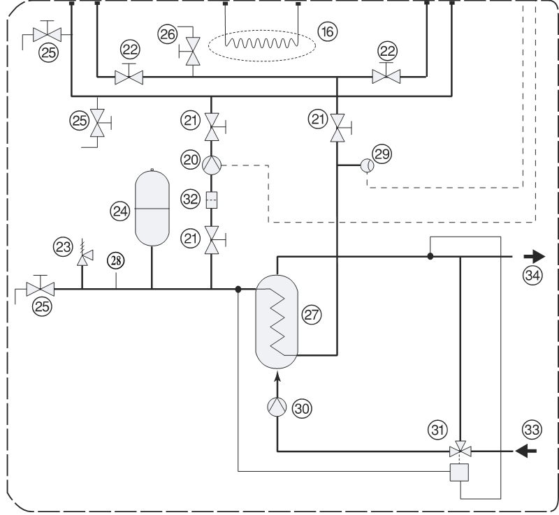
This figure only analyzes
20 Primary Pump (Heat uptake of the Retrievers)
29 Flow switch (must check flow rate)
30 Secondary Pump (Domestic Hot Water Circuit)
31 Three-way valve + controller.
34 Outlet temperature to preheat accumulator
- Pump commissioning (20)
- There is a need for hot water demand.
- In case the preheat accumulator is at a higher temperature than can be provided, pump 20 would not come into operation
- If it comes into operation, it would start up when the first compressor enters.
- It would be disconnected when the last compressor is disconnected and the chiller stops.
- There is a need for hot water demand.
- Pump commissioning (30)
- It needs to work at the same time as the pump 20
- Flow Controller (29)
- If there is no flow, alarm is triggered and the pump is disconnected (20)
- When disconnecting the pump (20) the pump (30) is also disconnected.
- Minimum Temperature Inlet to Retriever (3) of machine.
- Manufacturers set a minimum temperature with partial recovery (for example 25ºC.)
- The regulation of this temperature is carried out by acting on the 3-way valve (31).
- If it is less than 25ºC, the recirculation of the circuit controlled by the pump (30), is carried out through the central line of the 3-way valve.
- 3-way valve + controller (31)
- Guarantees the water supply at more than 25ºC., to the recoverers (3)
- When the sanitary water (34) is greater than the temperature of the preheat accumulator by several degrees, and it is true that the inlet A (3) is greater than 25ºC., the three-way valve allows the entire flow to pass through.
- If the water in the preheat accumulator is equal to or less than the water provided, closes the step (34) is recirculated through the 3-way valve.
- For this, the production temperature must be higher than the accumulated temperature. If not, it would disconnect the pumps (20) and (30)
- Flow regulation Pumps (20 and 30)
- The heat energy produced as indicated depends on several parameters, so it is highly variable.
- It is absurd to invest a high energy consumption for pumping, at times when very little energy is captured.
- Therefore, it is recommended that these pumps are equipped with speed variation and adapt their flow to energy production at all times.
- Increase in the production of domestic hot water
- It is possible to increase the production of DHW, increasing the condensation temperature.
- Because this option represents a cost increase in refrigeration production, it would be made within the parameters in which it can be profitable compared to the energies used to produce ACS.
Conclusions
- The production of DHW represents high energy consumption in the hotel facilities.
- Whenever it is necessary to produce refrigeration, it is necessary to dissipate heat.
- In a conventional chiller the heat is dissipated to the outside.
- Recovery chillers are standard chillers to which a heat recuperator is incorporated.
- Heat recovery can be:
- Partial
- It is the one that is usually installed in hotels.
- Total
- Partial
- In a partial recovery, a significant amount of heat energy dissipated by the chiller is used.
- It depends on variables such as the outside temperature and the number of compressors in service.
- It can be between 15% and 30% of the dissipated energy.
- It is possible to increase heat recovery.
- For this, it is necessary to increase the condensation temperature, with the consequent energy consumption.
- It would only be feasible when it is profitable.
- In addition to domestic hot water, other services such as heating pools, spas, Jacuzzi or any other heat need that arises can be attended.
- The energy contribution of the chiller to the production of domestic hot water has to be made in the preheat accumulators, because the contribution is highly variable and will depend on the refrigeration energy that is necessary to produce at all times.
- therefore it cannot guarantee 60ºC. in the heating accumulator.
- The accumulator from which the DHW departs must be at a minimum temperature of 60ºC., and have a reliable energy source that guarantees this temperature at all times, to combat the legionella bacteria.
- The integration of the chiller in the production of hot water requires a technical study.
- The design is made in accordance with the requirements of the regulations of each country and the manufacturer of the chiller.
- To extract the energy produced in the chillers and transmit it to the preheating circuit, pump groups are necessary.
- Given the variability of the conditions in the production, it is recommended that they be of variable flow.
- In this way, energy consumption is only necessary.
- Fixed flow pump groups significantly increase energy consumption in pumping.
- Given the variability of the conditions in the production, it is recommended that they be of variable flow.
- It is necessary to establish a control system that allows extracting the energy contribution produced by the chiller at all times, ensuring the correct operation of machinery elements and equipment.
- Thermal installations need to be served by qualified technicians who know the techniques applicable to them.
- The regulations for thermal installations requires preventive maintenance carried out by qualified companies that have to be perfectly documented.
- Good preventive maintenance reduces energy consumption, prevents breakdowns and increases comfort
- We Resolve as a company of integral maintenance of unique buildings, with extensive experience and implementation in the hotel sector (in Spain and America), has a technical department in which the pathologies, integration, optimization and improvements that occur in the field of facilities are analyzed.
- In the case of the free production of the DHW with a relatively small investment, a lifetime return is obtained, with the amortization periods being relatively fast.
- Reducing energy consumption represents a significant reduction in production costs, increasing sustainability and reducing environmental impact.
Literature
THERMAL INSTALLATION REGULATION
https://www.miteco.gob.es/es/energia/eficiencia/rite.html
We resolve case studies (energy optimization in refrigeration production)
Technical guide “Saving and recovery of energy in air conditioning facilities
Technical Guide Domestic Hot Water
Carrier Technical Catalogs
https://www.carrier.com/commercial/es/es/soluciones/coolers/coolers-air-agua/30rb—30rbp
1/08/2025
José Arroyo Martín
Ingeniero Tecnico Industrial en Electricidad y Mecánica