


analysis systems of
management in the
cold production
and heat in
Installations
hotels
Introduction
The management and control systems in thermal installations have the mission of adjusting the production and distribution of cold and heat to the real demand, to achieve maximum comfort with minimum energy consumption, thus reducing the environmental impact.
Energy optimization not only reduces costs, but also contributes to sustainable practices, an aspect valued by both customers and investors.
In the hotel facilities, the production of cold and heat represents the highest energy consumption.
The management and control systems integrate production machinery that have their own controls and other machinery and elements that respond to direct orders.
A management and control system has to know the singularities of each machine and the controls it is equipped with, taking advantage of its resources, without interfering with its operations.
If the management and control system is not correctly implemented and managed, there are disturbances in the operation that affect comfort and penalize and sometimes severely energy consumption, it is a source of breakdowns and reduces the useful life of machinery elements and equipment.
This article analyzes the approach that needs to be given to a management and control system in the production of cooling and heating of a centralized facility.
There is a perception that centralized systems have a higher consumption than variable refrigerant volume systems and that perception is sometimes based on objective facts, when comparing perfectly programmed systems, such as those of variable refrigerants, with systems managed by various actors in which multiple elements intervene and requires of a design and a programming carried out by technicians with a high degree of qualification.
It is true that numerous pathologies are observed in the technical audits carried out on production systems in thermal installations that penalize energy consumption. It is not the system that fails, they are incorrect designs, poor executions, technical ignorance of poor operation and maintenance.
A perfectly designed and maintained centralized installation is enormously flexible, more durable, more ecological and energy consumption must be lower, allowing complementary options that make it highly competitive.
All heat and cold production systems are valid and must be applied to specific installations, although in a large installation such as a hotel complex, the best option is a centralized installation, yes, it works in a similar way to VRVs in the optimization of resources.
Origin of control in thermal installations
In thermal installations there are two perfectly defined sectors
Production
- where the generators that produce cold or heat are located
Distribution
- It carries the energy produced to the terminal units (climatizers, fancoils, exchangers)
The energy that is produced and distributed has a confluence point, the general collector.
- In a centralized installation there are two general collectors
- cold
- Hot
- They receive the energy produced in generators.
- It is the origin of the distribution to terminal units.
General collector
The following pathologies are observed in an important number of the audited facilities:
- The hydraulic connections of the general collector are incorrect.
- The installation control probe is not correctly located.
The following physical parameters are involved in a general collector:
Pressure
- In a general collector located in horizontal the pressure is always the same, both in a state of rest and in operation.
Flow
The flow is variable
- The flow direction varies, depending on the primary and secondary circuits that are in operation.
Should a shut-off valve be installed in the general manifold?
Never
as the flows of the different primary and secondary circuits.
Generally the flow rate in the secondary is higher than the primary, although not always. There will be times when there is no energy supply from the generators and the circulating flow will be only secondary.
temperatures
- The temperature throughout a general collector is variable.
- Keep in mind that the transmission of heat in the fluids is carried out by convection, so that there will be significant differences in temperature in the collector while it is in operation.
- They will only be unified when the installation is out of service.
Control probe location
The installation control probe is a temperature probe that governs the installation and is located in the general collector.
Logically there are two general collectors (cold and heat) and two control probes (cold and heat)
Where is the probe installed?
In the general collector area, which ensures the same outlet temperature to all secondary circuits.
Pathologies found in the control point of thermal installations
- From the analysis of a large number of existing installations, it is found that in many of them, that the control probe is not correctly located.
- in some cases for not choosing the ideal point.
- in others by pathologies in the hydraulic connections of the general collector.
- As a consequence, it produces:
- high energy consumption.
- The start and stop number of the generators is increased.
- high energy consumption.
- Poor operation of the installation, not being possible to guarantee comfort:
- Secondary circuits that do not provide the necessary energy to the terminal units.
- If the temperature is higher than that required in refrigeration, the power provided by the terminal does not cover the requirements of the installation.
- The same happens if the temperature provided in heating, if it is lower. Nor does it cover the requirements.
- Secondary circuits that do not provide the necessary energy to the terminal units.
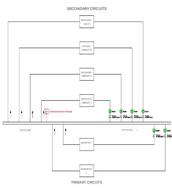
The general collector is correctly designed.
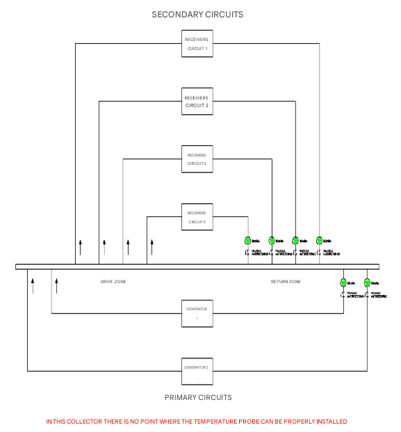
With this typology, at any point the control probe is placed does not give an exact reference and cannot control the installation.
slogans in the production of cold and heat
In a centralized installation that has a management system made up of several generators and several receiver circuits, it is necessary to establish instructions:
control setpoint
- It corresponds to the output temperature to the circuits corresponding to the terminal units.
- It is measured with the control probe located in the general collector.
Generator setpoints
It is the one located in the generators themselves (chillers, heat pumps, boilers).
- It must always be related to the control setpoint.
- must be somewhat lower in refrigeration
- It must be somewhat higher in heating
example.
- The control setpoint for cold circuits is 10ºC.
- In view of the installation, for example, the differential in the generators of 1.5ºC is fixed.
- The setpoints of cold generators will be (10-1.5) = 8.5ºC.
Stop gear differential
- Frequent starts and stops of generators suppose a relatively high energy consumption.
- Therefore, it is necessary to establish a differential between the stop and march orders.
- These setpoints are referenced to the one that measures the installation control probe.
Example:
- Control setpoint (output to secondary circuits): 10ºC.
- Differential between start and stop: 4ºC.
- The generators will disconnect when the setpoint is 10ºC, with the timing that is established.
- When the disconnect has occurred, it will not give the activation order to the generators until the control probe does not detect a temperature of (10+4) = 14ºC.
- between 10ºC. and 14ºC., the generators will be out of service.
- When the generators are started, they will produce water at a somewhat lower temperature setpoint of generators (10-1.5) = 8.5ºC.
Setpoint temperatures in generators
- All generators must have the same slogan and always referenced to the distribution.
- It is not correct to set different production temperatures.
- It will be the management system that enables the entry of the different generators.
How does the control setpoint work?
- The control setpoint always maintains the water outlet temperature at the set value.
- The probe will continuously inform the management and control system, so that it activates and deactivates generators based on the established programming.
Example
- A control setpoint of 10º C is set.
- The water should always come out at 10º C.
- If it comes out at a higher temperature, give the order to increase the refrigeration production.
- If it comes out at a lower temperature, it gives the order to reduce the refrigeration production.
- When it goes down from 10ºC, during the programmed time it gives the disconnection order.
- Once disconnected, when you reach the set differential between disconnect and connection (example 4ºC.)
- Give the connection order for (10+4) = 14ºC.
- and from there it always maintains the setpoint of 10ºC.
Operation of the management system in the production of cold and heat
For a management and control system to be fully efficient, it is necessary to establish communication with the generators.
Clarify that the generators have their own control and there cannot and should not enter an external management and control system, although in the sequences allowed by the manufacturer.
example.
- The internal control of a chiller has some deactivation techniques when it receives the stop command. It doesn’t stop immediately, but after a while.
- If an external control system intends to disconnect it, for example, cutting off the power supply, it will end up causing breakdowns.
- Therefore, the external management and control system gives you the stop order and the chiller stops with the sequence established in its own control.
Heat and cold production
In the production of heat and cold, they must exist:
- control setpoint (it is detected by the probe located in the general collector).
- Generator setpoint (something cold and somewhat higher in heat)
- Stop-run differential (avoids frequent connections and disconnections of generators)
At the moment the control setpoint is modified, the setpoints of the generators must automatically be modified.
Example
- CONTROL CONTROL 10ºC.
- Differential between control setpoint and generator setpoint 1.5ºC.
- Generator setpoint (10-1.5) = 8.5ºC.
- If the control setpoint is modified and set at 12ºC, the generator setpoint must be at that moment (12-1.5) = 10.5ºC.
Generator management
Regardless of the number of generators, their management must be carried out from the management and control system, as if it were only one.
This optimizes the power working at partial load.
Any action in both the installation and the generators is carried out from the central control station.
What happens if there is no communication gateway between control and generators?
energy consumption is higher.
It is possible to optimize at least partially powers, although not with the guarantee in the performance that provides total communication.
In that case, it would be necessary to program independently:
- control setpoint
- Generator setpoint
It is necessary that they are synchronized and when the setpoint is modified in control, the generator has to be modified.
Examples
- Day night function.
- It consists of establishing different slogans in the day and at night.
- You have to schedule that the setpoint in control and generators enter at the same time.
- It is programmed in control.
- It must be programmed in the control of each generator.
- Variation of setpoints based on outdoor temperatures
- It is programmed in control.
- It must be programmed in the control of each generator.
Wrong programming in management systems for cold and heat production
In the production of cold and heat, programming errors are sometimes observed.
Starting and stopping of generators
- Programs have been observed for the operation of large generators as if they were small domestic consoles.
- This causes:
- Simultaneous input of generators
- Reduction of its useful life
- Faults
- If they are not increased, it is because manufacturers establish internal protection sequences between a stop and the subsequent run.
- Continuous maneuvers of electrical connection and disconnection elements that cause serious faults.
- Set of boilers for hot water production in summer that work simultaneously, when the energy demand is minimal.
- They only have to provide a small energy and two boilers enter
- stop immediately
- It starts after a few minutes to stop again.
- Keep in mind that every time it starts and for a boiler it is necessary to carry out a sweep of gases that cools the home, so a significant amount of energy is lost
Communications between generators and control system
When communication is via communication gateway, the control system manages the set of generators as if it were only one.
When not, it only manages certain parameters.
The control of the generator is the one that informs the management and control system of the operating conditions and the power it provides at all times.
In this way, the operation is optimized:
- partial load
- Floating setpoints in generators
- Taking variable control setpoints as reference
- night day
- Disconnection by outdoor temperatures
- generator alternations
- Alternations Pump Groups
- etc. etc
Starting stop of generators and associated pump groups
The generators have to receive an activation order to get up and running.
Each generator has an associated pump group that carries water (cold or hot) from the generator to the general collector.
The correct operation is as follows:
- The running order starts from the control setpoint (the one located in the general collector)
- First, the associated pump group is launched.
- After a few seconds, the generator is activated.
- According to the demand of the installation and the sequences of operation, one or more generators can enter.
Only one generator works
- The first generator is activated with the run order.
- If there is only one generator working, the management and control system should not give you the stop order, lets it continue to work.
- After a small period and since there is no energy demand, it is the same generator that is disconnected using the deactivation techniques of its own control.
- The management system must know that the generator has disconnected.
Example:
- A control setpoint is set in the drive to secondary circuits of the general collector of 10ºC.
- The control probe continuously informs the temperature management system.
- A differential between stop and gear of 4ºC is set.
- As long as the temperature detected by the control probe is greater than (10+4) = 14ºC, the management and control system starts the pump associated with the generator.
- With the set timing, it starts the generator.
- The generator is activated and produces cold water at a somewhat lower temperature and according to its setpoint, for example of (10-1.5) = 8.5ºC.
- When it meets the demand, the generator is deactivated by its own internal control.
- At that time the management system receives the information and:
- It does not give the generator run command again until the control probe (10+4) = 14ºC is detected.
- Disconnects the pump associated with the generator after the set timer.
Several generators work
- In a properly designed system with communication between distribution and generation controls, the set functions as a single generator.
- In this case, the management system is the one that gives order of deactivation to all the generators and associated pumps, until only one remains in operation.
- If there is no communication gateway, it will be the management system that connects and disconnects the different generators and associated pumps according to the information that can be extracted from the control of the generators until only one remains in operation.
- When only one remains in operation, the disconnection must be carried out by the generator’s own control.
- When any of the generators stop, it informs the control system so that it proceeds to disconnect the associated pump.
Generator connection and disconnection
as indicated
a generator:
- must be connected by the control system.
- You must disconnect using the deactivation techniques of your own control system.
- The control system must know that it has disconnected to act on the associated pump.
Various generators:
- must be connected by the control system.
- must be disconnected by the control system.
- You must inform the control system that you have disconnected to act on the associated pump.
- When one remains, the operation is indicated for a generator.
Energy optimization in cold and heat production
Partial load operation
The yields in the generators for the production of cold and heat are superior working at partial load, whether it is:
- chillers
- heat pump
- conventional boilers
- Condensing boilers
- In the latter, the yield is increased by the energy use of condensation.
When there are several generators, the management and control system is the one that must manage their inputs and outputs, through communication gateways and based on the percentage of power provided at each moment.
Use of external conditions in energy production
The terminal units (climatizers and fancoils) provide a power to the enclosure that is a function of the inlet temperature of the heat transfer fluid, generally water.
The energy needs of the enclosures depend on a series of variables, among which the external conditions stand out.
- It is not the same as the outside temperature is 33ºC. in summer, or make it 25ºC.
Based on this, an operating ramp can be established by adjusting the water outlet temperature in the secondary circuits.
Example in refrigeration
- If when the temperature is 33ºC, water is required at 9ºC.
- and when the temperature is 25ºC, water is required at 13ºC.
- The control setpoint must be continuously modified, taking the outside temperature as a reference.
The same criterion is transferred to the generators
In the example indicated:
- If a differential of 1.5ºC is adopted when starting up.,
- When a distribution temperature of 9ºC is required, the production temperature will be:
- (9-1.5) = 7.5ºC.
- When it is 13ºC, it would leave the generator at
- (13-1.5) = 10.5ºC.
- These are floating slogans that are continually modified taking the outside temperature as a reference.
What is achieved with it?
- Reduce energy consumption and increase comfort.
How does comfort improve?
- Whenever the airflow temperature in the terminal units is closer to the enclosure temperature:
- The air vein leaves the terminal units with less temperature difference.
- In winter, when leaving at a lower temperature, the relative humidity of the air vein is higher (less dry air).
How is energy consumption reduced?
- Reducing energy consumption is important
in the distribution
- Transmission losses in the hydraulic circuits between general collector and terminal units are reduced by reducing the temperature difference between the fluid (water) and the environment.
in production
- In a compression refrigerated system (chiller, heat pump), energy consumption is lower if the temperature difference between evaporation and condensation is reduced.
- It also happens in boilers.
- Performance increases when the temperature of the hot water produced is reduced.
- If the boiler is condensing, it can also recover a higher percentage of water vapor from the smoke, increasing its performance.
In the latent heat reduction
- In summer operation there is a significant amount of energy that is used to condense the water vapor contained in the air.
- As the temperature increases, the condensation decreases.
OPERATION NIGHT DAY
The operating conditions are different during the day and at night.
- In the case of refrigeration, the distribution temperature can be increased and, based on this, cold production.
- In heat pump, the distribution temperature can be reduced and based on this, the production of heat.
- The same would happen in boilers (the fumes come out at a lower temperature).
- In condensing boilers, condensation heat is also used.
In night operation, the differential between stop and gear can also be increased, so the generators would reduce the number of starts and stops to a greater extent.
Generator disconnection
From the management and control system, we proceed to:
- Disconnection of generators as energy demand is reduced.
- provided that all secondary circuits are out of service.
- If external conditions make it possible
- at night with favorable external temperatures
- would disconnect the distribution circuits
- They would disconnect the generators
- at night with favorable external temperatures
bomb groups
When a generator stops working, the pump group associated with the set timing must be disconnected.
Pump groups represent a relatively significant energy consumption.
It is observed in some installations that when the generator is enabled, its associated pump group continuously operates, which represents useless and unnecessary energy consumption.
It is produced by two assumptions
- poor programming, which puts it on continuously
- poor control programming
- Generally the control disconnects the generators
- When you give the disconnection order, it establishes a high timing and higher than that required, because it does not know which power step is working and is positioned on the security side.
- The associated pump group gives the same timing plus an additional one so that it always disconnects afterwards.
- If, for example, set 600 seconds to disconnect the generator
- And 600 + 120 seconds to disconnect the pump, reality can be very different.
- The generator has probably been disconnected after 100 seconds
- The pump, once the generator has been disconnected, it is convenient that it continues to function a few more seconds, for example 30
- If the generator informs the control system that it is disconnected.
- The control system must disconnect the pump within 30 seconds after disconnecting the generator.
- In that case it would work 130 seconds instead of 720 programmed.
lack of coordination in slogans
It is relatively frequent.
It is observed on many occasions that the control setpoints are not coordinated with the generator setpoints. If a communication gateway does not exist, the generator setpoints must be programmed.
Two assumptions can be given
- a production temperature much lower than the setpoint of the collector
- a production temperature higher than the setpoint of the collector
Examples:
The following setpoints are established in control for night-day operation (much lower temperature in production)
During the day: 9ºC.
Overnight: 12ºC.
It is estimated that the temperature difference between drive and return is 3ºC.
The chiller control is set at 7ºC.
The chiller running stop is done from control.
- It is common in management and control systems.
It is considered the generator in operation.
What happens at night?
- The chiller will always produce water at 7ºC.
- The water it receives from the installation will be of the order of 15ºC.
- 12ºC. of slogan
- increase of 3ºC.in return.
- to lower the temperature of 15ºC. At 7ºC, the chiller can perfectly reach 100% of its nominal power, although it is night and the energy consumption of the installation is low.
- When the chiller is at 100%, it detects the control probe 12ºC. in the general collector and orders the stoppage of the chiller.
- The management and control system orders the chiller to stop when it can be at 100% of its nominal power.
- The performance is very poor, apart from consuming a lot of energy, it subjects the chiller to unnecessary stress.
- In this case, energy consumption is seriously penalized by:
- produce water at a lower temperature than necessary
- cause a full load chiller operation, which is when it has less performance.
- It is the same effect as if we see a red light at 100 meters, we accelerate the car to the maximum and we give a brake.
The following setpoints are established in control and generators (higher temperature in production)
Control setpoint: 9ºC.
Chiller setpoint 11º C.
What happens in that case?
- In no case is the temperature of 9ºC, because it is being produced at 11ºC.
- Therefore, the chiller will always be enabled, because the 9ºC can not be reached in the drive, established in the setpoint.
- The associated pump group never stops when the chiller is enabled.
- The cooler however does stop due to its internal controls when it has been producing water below 11ºC for some time.
- The installation keeps it activated so that after the minimum time set by the manufacturer in its internal control, the chiller starts again and after a short time to stop and so on
- The performance of the installation is very poor, consumes a lot of energy and subjects the chiller to unnecessary stress.
Impact of maintenance on comfort and sustainability
Maintenance in thermal installations is not only mandatory but is also essential for a comfortable and sustainable operation of cold and heat production facilities.
Maintenance must be carried out by authorized companies and all actions must be documented.
All this is specified in Table 3.3 of IT 3.3 of the RITE.
A management system in which there is a communication gateway with the generators can offer the maintainer a series of parameters with alerts that avoid unnecessary energy consumption, anticipating possible failures, as well as adjustments that optimize energy consumption.
Qualified companies supported by apartments. engineering, they can offer the property advice on the management and control systems that allow effective energy savings.
A good maintenance carried out by qualified professionals, ensures correct operation, improves comfort, reduces energy consumption, prevents the appearance of breakdowns, increases the useful life of the machine, elements and equipment and makes the installation more sustainable.
Conclusions.
This article analyzes the energy optimization in the production of refrigeration and heating in centralized facilities that have several generators and management and control system.
The production of cold and heat represents the highest energy consumption in the hotel facilities.
The origin of the management and control is located at the output of the general collector to the terminal units (climatizers, fancoils, exchangers)
The production of cold and heat in the generators must be coordinated with the control setpoint established in the general collector.
The ideal is to establish a communication gateway between the management and control post and the controls of the generators.
- With this you can manage the operation of all generators as if it were only one.
- It allows to know all the operating parameters of the machines.
When there is no communication gateway, the schedules for generators are not possible to carry out from the central management and control post.
- In this case, energy consumption is higher
- Unable to properly manage partial load operation
- The instructions in the machines must be implemented by acting on the control of each generator.
It is very important to establish the control setpoint of the installation taking into account:
- Set a drive temperature depending on external conditions
- Set complementary criteria night day
- Establish a relatively high differential between running and stop
- There is less start and stops
- The centralized installations normally have an important mass of water, so comfort will not be affected.
- Establish a coordinated slogan in the production of generators.
In the technical audits, a generalized trend is observed in the controls to activate the start-up and stoppage of generators and pumps associated with them.
In some cases, the existence of uncoordinated slogans between control and generator that have the following consequences is verified:
- The energy consumption in the generators is higher by increasing the difference between evaporation and condensation.
- In the case of boilers, they produce hot water at a higher temperature.
- Generators stop orders are given when they are developing high power.
- The associated pumps work longer than necessary.
In the hot or cold water distribution to the terminal units if the temperature parameters can be set:
- Transmission losses decrease
- Latent heat losses due to condensation in summer decrease
- When the generator is a boiler, the performance is increased and in the case of condensing boilers in a notable way.
In the technical audits carried out on management and control systems, pathologies are detected in the production of cold and heat that have different origins.
- Incorrect hydraulic connections
- Incorrect location of the control probe
- Lack of user and maintenance manual indicating the person responsible how the installation should work.
- Incorrect communications between distribution and production systems.
- The control company has not received any reference to how the installation has to be scheduled.
- They are programmers and their function is to program what appears in the project and indicates the use and maintenance manual.
- They do not have to know the techniques of production of cold or heat.
- uncoordinated slogans.
- poor maintenance.
On the other hand, substitutions of generators are observed that have been entrusted to apartments. shopping for hotels.
- They contact the supplier and request the most similar.
- Regarding control.
- A generator for cold or heat requires an exhaustive technical analysis that adapts to the latest technologies with optional that do not come as standard.
- It is totally necessary in the new generators to integrate the option offered by the manufacturer of communication with the management and control system.
- In addition, pumping equipment between generator and variable speed collector must be implemented, so energy savings are significant.
We Resolve as a company of integral maintenance of unique buildings, with extensive experience and implementation in the hotel sector (in Spain and America), has a technical department in which the pathologies, optimization and improvements that occur in the field of facilities are analyzed.
The Engineering Department has carried out numerous technical audits and, based on them, solutions have been designed to significantly improve comfort and energy consumption.
It is about seeking the adaptability of the existing facilities, due to economic technical difficulties of a certain consideration in some cases, which forces the (R&D&I) to be applied by investigating the pathology of the existing installation, development of techniques that allows its implementation with the lowest cost and innovating in the optimization of resources to achieve Improve comfort and reduce energy consumption, very important in this type of installation and that contribute greatly to improving sustainability.
Literature
THERMAL INSTALLATION REGULATION
https://www.miteco.gob.es/es/energia/eficiencia/rite.html
Articles Web Page We Resolve
https://weresolve.es/category/Cases-de-estudio-Tecnicos
- Hydraulic connections in general thermal installation collectors
- Analysis of VRV and centralized compression refrigeration systems
Energy optimization Refrigeration production in hotel facilities
25/03/2025
José Arroyo Martín
Ingeniero Tecnico Industrial en Electricidad y Mecánica