

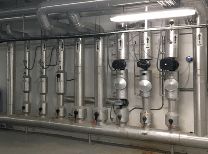
Introduction
1
We Resolve as a company of comprehensive maintenance of unique buildings, with extensive experience in the hotel sector (in Spain and America), has collaborated in the diagnosis, treatment and resolution of multiple pathologies in the field of facilities.
It is the company’s philosophy to collaborate as much as possible to reduce the environmental impact through a series of actions that range from the continuous training and qualification of all its personnel, to the contribution of R&D&I (research, development and innovation) in all its actions.
It is for this reason that he has considered it convenient to share a series of experiences based on real cases, which will undoubtedly serve to detect pathologies and seek the pertinent technical solutions.
The purpose is to reduce energy consumption, operating costs, while increasing comfort and sustainability, contributing as much as possible to achieve a cleaner planet.
The article has been written with a language within the reach of maintenance managers and technicians and will serve to detect pathologies, which are possible have gone unnoticed, even if their consequences are suffered.
Initial clarifications
1
This article analyzes the hydraulic connections in the general collectors of thermal installations.
The production and distribution of heat and refrigeration is part of all hotel facilities.
In the general collectors, the energy produced by the generators is received and it is distributed to the terminal units (receivers).
An incorrect design and execution poses problems that are difficult to solve.
We Resolve has resolved serious pathologies in general collector designs and executions.
In the illustrations, graphics of “Comments to the RITE 2007 (Regulation of Thermal Installations in Buildings) edited by IDAE are used, indicating the section and page, and others of their own elaboration.
incidence of pathologies in the functioning
1
- areas where the necessary hygrothermal conditions are not achieved
- In general, comfort is not guaranteed.
- High energy consumption
consequences of pathologies
1
- Complaints and discomfort from customers due to poor operation.
- In some cases, non-compliance with current regulations
- Submits machinery and equipment to a higher or far superior operation than necessary:
- more maintenance
- Fault risk
- Reduction of the useful life of machinery and elements.
- Cost increase
- Increased energy consumption
- Higher fuel consumption
- higher electricity consumption
- As a consequence, greater contamination, causing a serious environmental impact.
What is a general collector?
1
General collector It is the element where the hydraulic connections of generators and receivers are made.
It receives the energy from the generators and distributes it to the terminal units or receivers.
In the general collector, the drive is grouped in one zone and the return is grouped in another, although between them there can and neither should there be any cut-out element.
In thermal installations, there are two general collectors:
- General refrigeration collector
- General heating manifold
Circuits from generators (primary circuits)
- boilers
- chillers
- Heat pumps
- any renewable energy system
[Generador = Generator
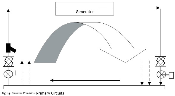
Comments to the RITE 2007 (p. 49)
- This scheme represents primary circuits (corresponding to generators).
- One has been developed, the others on dotted lines.
- The elements represented are:
- left branch
- Cutoff valve
- anti-vibrator
- Filter
- Central Branch (Generator)
- Generator
- A large arrow representing the movement of the fluid. (it is done by a bomb group)
- Right Branch
- anti-vibrator
- Motorized valve (not always necessary)
- A check valve is necessary in the circuit to ensure that the flow always goes in the same direction.
- left branch
Distribution Circuits to Receivers (Secondary Circuits)
- exchanger to produce hot water
- fancoil
- air conditioner
- Radiator
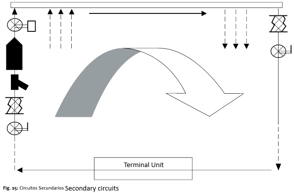
Comments to Rite 2007 (p. 51)
- This scheme represents secondary circuits (corresponding to receivers).
- One has been developed, the others on dotted lines.
- The elements represented are:
- left branch
- Cutoff valve
- anti-vibrator
- Filter
- Motorized valve (not always necessary)
- Central Branch (Terminal Unit)
- Receivers (terminal units)
- A large arrow representing the movement of the fluid. (it is done by a bomb group)
- Right Branch
- anti-vibrator
- Cutoff valve
- A check valve is necessary in the circuit to ensure that the flow always goes in the same direction.
- left branch
In the general collector there is always a mixture of the heat transfer fluid (usually water) provided by the generators and sent to receivers.
What is the mission that the general collector must fulfill?
- that all secondary circuits (drive to receivers) have the same output temperature
How do you get?
- Making correct hydraulic connections
What is the reality of the facilities?
- In many cases it is observed:
- Incorrect schemes that are part of projects
- Wrong mounts
What is the consequence?
- The heat transfer fluid (usually water) is sent to the secondary circuits at different temperatures, so the required comfort parameters are not achieved.
Is it easy to correct pathologies?
- Usually not.
- These are integrated tubes in an existing installation within a machine room that requires complex action.
- There will be cases in which it is necessary to address the complexity and proceed to its correction.
What is the solution then?
- A technical analysis of the installation in which the disturbances caused by an incorrect installation are analyzed.
- There are many possibilities of connections in a general collector and there are many pathologies that occur.
- Drive situation
- Returns Situation
- required flows
- mixtures that are produced
- essential circuits.
- Flow settings
- Receivers that work in winter or summer
- etc.
Hydraulic connections in the general collector
1
There are hydraulic connections with:
- Generators (primary circuit)
- Receivers (secondary circuit)
flows
- Flows in a general collector are variable.
- It depends if there are one or more generators
- If all or only part of the receiver circuits are in operation.
- Generally the flows corresponding to the secondary circuits are higher than the primary circuits.
- Two cases can usually occur:
Higher secondary flow (the most common case)
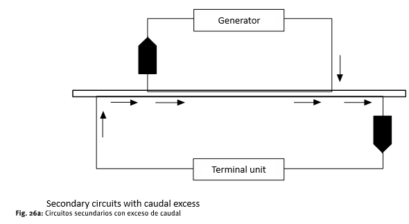
Comments to the RITE 2007 (p. 52)
- through the secondary one circulates a greater flow than through the primary
- For the explanation to be intuitive, let us consider that 100 liters/minute circulate through the primary (generator) and 200 liters/minute circulate through the secondary (terminal unit).
- In that case, the central area of the collector circulates:
- 200-100 = 100 liters/minute.
- The direction of flow is indicated in Figure
Higher primary flow (less common case)
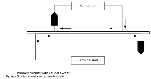
Comments to the RITE 2007 (p. 52)
- through the primary circulates a greater flow than through the secondary
- For the explanation to be intuitive, let us consider that 200 liters/minute circulate through the primary (generator) and the secondary (terminal unit) circulates 100 liters/minute.
- In that case, the central area of the collector circulates:
- 200-100 = 100 liters/minute.
- The direction of flow is indicated in Figure
same primary and secondary flow
- If at a given moment the same flow circulates through the primary and secondary circuit, there is no fluid passage through the central area of the collector.
Analysis of connections
1
In a general collector of thermal installations, it always has to exist in relation to the secondary circuits:
- drive zone
- return zone
The main objective that a general collector must meet is that the drive to all secondary circuits (receivers), must be at the same temperature.
In the schematic representation that follows, only the pump and the non-return valve are indicated, dispensing with the rest of the valves and accessories.
This article represents two typologies, 1 which is incorrect and 2 is correct.
Typology 1
SE  observe in many installations.
It is an incorrect configuration and gives rise to pathologies that are difficult to solve.
To facilitate understanding, it will be considered that all the pumps, both from the primary and secondary ones, move the same flow rate.
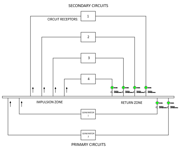
The figure shows:
- 4 secondary or receiver circuits
- 2 primary or generator circuits
- The flow directions in each of the circuits
- All pumps are considered to move the same flow rate.
Assumption 1 (only fluid circulates through all secondary)
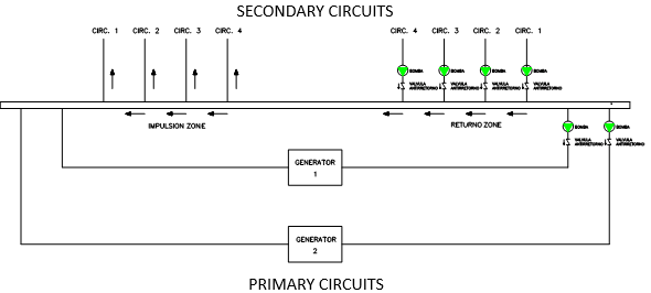
- The primary pumps are stopped and there is no fluid passage.
- those of the secondary are in operation.
- The direction of flow is always the same
Assumption 2 (circulates fluid by secondary and generator 1)
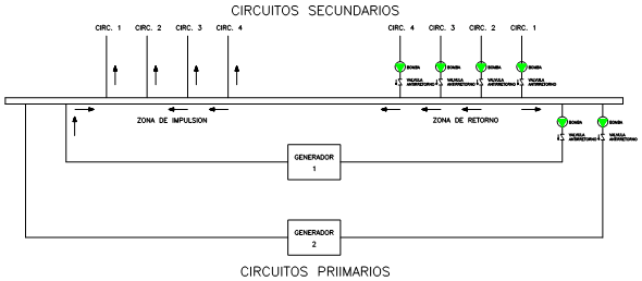
- The generator pump 1 and the secondary circuits are in operation.
- Generator 2 pump is out of service.
- The direction of flow is variable
- The flow of water at the temperature produced by generator 1, is fully collected by circuit 1, as it is the closest to the connection.
- Circuits 2, 3 and 4 bypass the water from the collector, without receiving energy from the generators.
- Therefore all receivers connected to 2,3 and 4, it is as if they did not exist.
Assumption 3 (circulates fluid through secondary and generators 1 and 2)
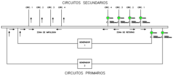
- In operation all primary and secondary pumps.
- The flow direction is variable.
- The flow of water at the temperatures that is produced by generators 1 and 2, is fully collected by circuits 1 and 2, as they are the closest to the connection.
- Circuits 3 and 4 bypass the water from the collector, without receiving energy from the generators.
- Therefore all the receivers connected to 3 and 4, it is as if they did not exist.
Typology 2
The same hydraulic circuit is analyzed with a correct configuration, applying the criteria set out above.
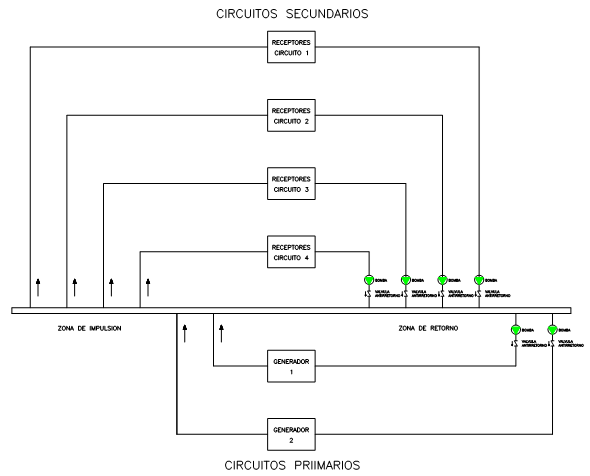
Assumption 1 (only fluid circulates through all secondary)
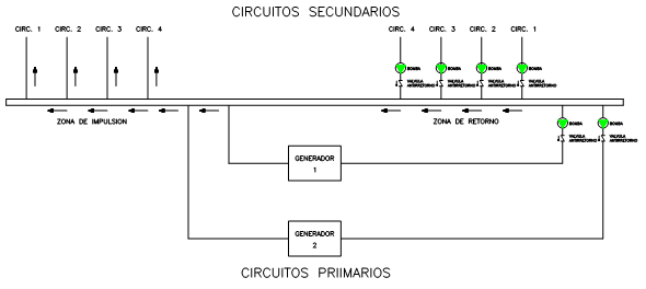
- The primary pumps are stopped and there is no passage of fluid
- The direction of flow is always the same
Assumption 2 (circulates fluid by secondary and generator 1)
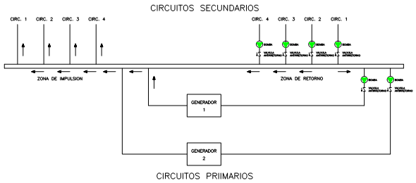
- Only the pump corresponding to the primary circuit of generator 1 and all of the secondary circuits works.
- The direction of flow is variable, although in impulse to receivers it is always the same.
- The mixture between generators and receivers occurs before the drives.
- All circuits drive at the same temperature.
Assumption 3 (circulates fluid through secondary and generators 1 and 2)
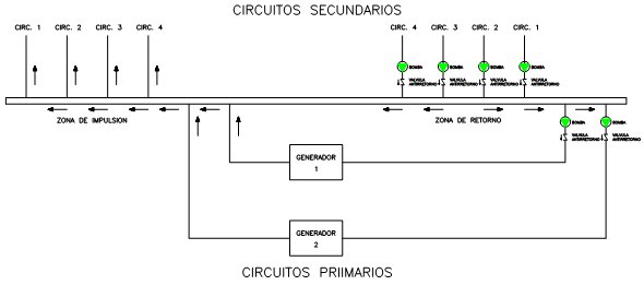
- All generator and receiver pumps work.
- The direction of flow is variable, although in impulse to receivers it is always the same.
- The mixture between generators and receivers occurs before the drives.
- All circuits drive at the same temperature.
Conclusions
1
In existing installations, many typologies of hydraulic connections are observed, a large part incorrect.
When the hydraulic connections are incorrect, the operation is poor.
Reform of hydraulic installations are complex and expensive.
A detailed analysis of these circuits may allow alternative solutions with acceptable operation.
The operating time of machines and elements is greater, so there is a potential risk of breakdowns and the period of useful life is reduced.
Energy consumption is high, which seriously affects the environmental impact and operating costs.
We Resolve has acted and solved pathologies of this type and can analyze, advise and solve any type of pathology that arises.
Literature
1
Rite 2007 comments
27/2/2024
José Arroyo Martín
Ingeniero Tecnico Industrial en Electricidad y Mecánica