

Introduction.
1
We Resolve has considered it convenient to include among its “cases of study”, the analysis of the expansion of water in thermal installations.
In the hotel sector, thermal installations are essential for the development of the activity.
Significant variations of temperature occur, which if not properly treated cause serious problems.
All elements involved must be carefully designed, implemented and maintained.
We Resolve has studied, analyzed and solved serious pathologies that appeared in the facilities that have had various origins, in the design, implementation and maintenance.
The origin of many of these pathologies lies in the non-existence of the mandatory use and maintenance manual.
The rite in its article 16 (project) section 3.d establishes:
The instructions for use and maintenance according to the specific characteristics of the installation, through the preparation of a «use and maintenance manual» that will contain the safety, handling and maneuvering instructions, as well as the programs of operation, preventive maintenance and energy management of the projected installation, in accordance with IT 3.
In Article 26 (Maintenance of the facilities) paragraph 2 specifies:
When taking charge of the maintenance, the owner of the facility will deliver to the representative of the maintaining company a copy of the “Manual of Use and Maintenance” of the thermal installation, contained in the building’s book.
The expansion vessel requires maintenance in which it is necessary to know not only the technical aspects of its operation, but also the regulation parameters that must be monitored and maintained.
These parameters are designed in project, modified if they proceed in the technical direction and included in the user manual and maintenance.
If this information is not available, it is not possible to guarantee proper maintenance.
Basics.
1
All bodies dilate with temperature.
- solid
- liquids
- gases
When dilating they increase their volume. (The same mass occupies a greater volume)
- Liquids are practically incompressible, with the pressures at which the facilities work.
- To compress a liquid significantly, a very high pressure is required.
- Gases are easily compressed.
In thermal installations, water is generally used as a heat transfer fluid (or with an antifreeze in very cold climates where there is a risk of freezing).
The properties of water are as follows:
- The maximum density is at 4°C. (1,000 kg./m3.)
- The minimum density is at 100ºC. (958.05 kg./m3.)
- At the pressure of 1 atmosphere, between 0ºC. and 100ºC., is found in the atmosphere in the form of liquid or steam.
1 atmosphere = 1.013 bar = 1.033 kgs./cm2. = 10.33 m.c.a. = 101,325 Pa
Expansion of water in thermal installations
1
Thermal installations are made up of closed circuits.
These circuits are initially filled with water and thus must be maintained throughout the life of the installation.
Water should only be added in case of breakage.
Let’s analyze the following circuit at sea level (pressure 1 atmosphere):
- Volume: 000 liters
- Initial filling temperature: 12ºC.
- Average temperature: 80ºC.
- DATA:
- density of water at 12ºC. 999.58 Kg./m3.
- density of water at 80ºC. 971.60 Kg./m3.
The mass of water with which the installation is filled at 12ºC., is 999.58 Kgs. and occupies a volume of one cubic meter.
If the mass of water is heated to an average temperature of 80ºC, taking into account the difference in densities, the volume it would occupy at the atmospheric pressure would be 1,028.80 liters
Therefore, where only 1,000 liters have to fit, 1,028.80 liters have to enter.
What’s the matter?
If the circuit is closed and does not find where to expand, this increase in volume creates a pressure on the pipes, generators, receivers and other elements that form it.
Such is the pressure that is generated, that it ends up breaking through the weakest site.
Neither the boiler, nor the receivers, nor the pipes, can withstand the increase in pressure that occurs.
What solutions can we apply?
As it is necessary to maintain the same water and be practically incompressible at working pressures, it is necessary to integrate some element into the circuit that is capable of absorbing this expansion.
Some time ago, the open expansion vessel was used, which consisted of a water tank in contact with the atmosphere, located at the highest point of the installation.
That deposit contained a smaller volume of water when it was cold and a larger volume when heated.
This solution is prohibited by the current RITE (Thermal Installation Regulations), due to the fact that the water is in contact with the air, heat loss and replenishments occur due to evaporation.
In the repositions together with the water, oxygen and mineral salts are provided.
Therefore, it is necessary to look for a system that allows absorbing the variations of the volume of the water, maintaining the pressures within admissible values.
This is achieved by installing closed expansion vessels.
closed expansion vessel
1
It consists of a closed pressure tank, with nitrogen or pressurized air, in which an elastic membrane is housed.
It is based on the principle of compressibility of gases.
The membrane is connected to the water circuit.
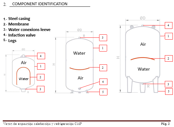
Instruction manual, installation, use and maintenance IBAIONDO
- The representation is schematic, because the membrane where the water is housed is completely closed and has no contact with the air.
- The water always enters through the point indicated as 3
- The air is always supplied or extracted by the point indicated as 4
As the temperature increases, the water dilates and fills the membrane housed inside the tank, thus compressing the air contained therein.
Indicate that once the pressure tank has been regulated, the air contained within it is always the same.
When the temperature drops, there is less volume of water in the circuit, the membrane is empty, it exerts less pressure and the air occupies most of the volume of the tank.
Between the hot water contained in the membrane and the air there is no contact.
What is the function of the expansion vessel?
- Maintain the pressure between a minimum and a maximum that guarantees correct operation, preventing generators, receivers and other elements from working in an environment of higher pressures than those that have been built.
- Contribute to the security of the installation, although it is not a specific element for security.
- Installation safety is entrusted to safety valves.
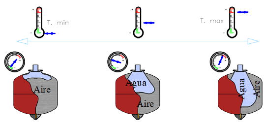
*Aire = Air, Agua = Water
Instruction manual, installation, use and maintenance IBAIONDO (p. 5)
- On the left the pressure in the installation is minimal. The water membrane is observed in an almost empty light blue color and the air occupies almost the entire tank.
- In the intermediate figure, when the temperature rises, the water has expanded and logically, when increasing the volume, it compresses the air. By reducing the volume of air, the pressure increases.
- On the right, the installation works at the maximum temperature, there has been a greater expansion of the water, the air is further compressed, reducing its volume and increasing the pressure.
Example
If the boiler is manufactured for a pressure of 4 bar in an installation, the maximum pressure of the installation will have to be less than 4 bar.
at 4 bar = 400 kPa. = 4,078 kgs./cm2.), the safety valve will have to be adjusted.
Logically, the expansion vessel must be calculated so that the maximum pressure reached by the installation is lower (recommended 3.5 bar.)
What criteria must be set to calculate an expansion vessel?
For the calculation of the expansion vessel, the following must be taken into account:
Fix your location within the circuit
- If the expansion vessel is installed as recommended before the pumps, the pressure will be the one corresponding to its location.
- If the expansion vessel is installed at the outlet of a pump group, to the pressure corresponding to the location place, you have to add the one provided by the pump.
- The initial pressures would be:
- Example before the pump
- An installation has the last receiving element at a height of 15 m, with respect to the point where the expansion vessel is installed.
- Therefore, the column of water that gravitates on the glass provides a gauge pressure of 15 m.c.a. (water column meter)
- Example after pump
- If the pump is installed after the pump pressure on the installation, add the one exerted by the pump on the glass.
- If this pressure is 12 m.c.a., the initial pressure is no longer 15 m, but of (15+12) = 27 m.c.a.
- Example before the pump
pressures
- Being clear about the concept of the pressures that are handled in the installation is very important.
- In this case, the following pressures are involved:
- minimum of installation.
- air pressure in the vessel.
- installation maximum.
Minimum installation pressure
- It is fixed taking into account:
- manometric height at the site of its location.
- Pressure increase due to pumping equipment, depending on its location.
- Initial overpressure that is fixed to prevent air intake.
- This initial overpressure is fixed by the designer and it is recommended that it be between 0.7 and 1 bar
Initial pressure of the vessel
- It is the pressure that the nitrogen or air that surrounds the membrane must exert.
- It should be around 0.2 or 0.3 bar below the minimum installation pressure.
- That way even with the minimum pressure of the installation there is a little water in the membrane, which prevents deterioration.
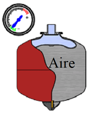
The minimum installation pressure is 0.2 or 0.3 bar higher than that of the air in the glass
maximum pressure
- minimum pressure.
- pressure increase due to water expansion.
- The maximum pressure is set taking into account the pressure that the installation elements support, and must always be less than the value calibrated for the safety valve.
- It is recommended that at least 0.5 bar remain below the safety valve.
Expansion vessel location
1
In principle, the expansion vessel can be installed at any point in the circuit.
In previous thermal installation regulations (RITE 98) it was forbidden to install a shutoff valve between the generator and the expansion vessel. It was based on the UNE 100157:1989 standard repealed on 11-12-2004, by the current 100155:2004.
At the time that the UNE 100157:1989 standard is repealed, it is allowed to install a cut-off between generator and expansion vessel, which is also necessary for maintenance.
Subsequently, the RITE 2007 appears, currently in force, with the complementary provisions that it has been implementing and modifying over the years, (the last one of 2021).
In the comments to the RITE 2007, it is recommended to install the expansion vessel in a single point, which is the one that serves as a reference, preferably placing it in the suction of the pump.
If several expansion vessels are installed at different points in the circuit, each one works in a different way and would have to be the subject of different calculations. It is not prohibited, although it is not recommended.
Indicate that the correct location is not a requirement. It will be the engineer in each case who determines, based on the characteristics of the installation, the most suitable location.
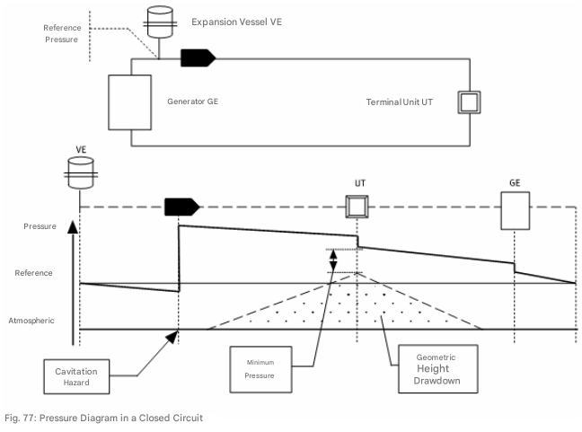
Comments to Rite 2007 (p. 112)
The hydraulic circuit appears at the top and the operating diagram at the bottom.
The circuit sequence is:
• VE expansion vessel
• Pump (represented by the filled arrow)
• UT terminal unit
• GE heat generator
In the diagram, the pressures on the ordinate axis are represented.
The expansion vessel sets the reference pressure of the installation.
- The pump groups need a positive aspiration pressure based on their constructive characteristics, so the situation of the vessel in its aspiration technically favors its function
- In the pressure diagram, a small drop in the reference pressure before the pump is observed, which corresponds to the loss of load in pipes and accessories in the section between expansion vessel and pump.
- The pump increases the pressure in the circuit and at its exit is the highest point of pressure of the installation.
- From the pump to the arrival at the terminal unit (Fancoil. Radiator, exchanger, etc.), there is a loss of load in the section of pipes that is represented with that inclined line.
- In the terminal unit there is a pressure loss.
- From the terminal unit to the generator there is a loss of pressure in the pipe.
- A pressure drop occurs in the generator.
- From the generator to the expansion vessel, a pressure loss occurs in the pipe.
Requirements in the expansion vessel installation
1
In the installation of the expansion vessel, it is necessary to meet some requirements:
Prevent air from entering the installation
• For this, it is necessary to establish an initial overpressure on the minimum.
• If the water when cooling and diminishing its volume does not completely fill the circuit, air enters the installation, due to atmospheric pressure.
• This overpressure has previously been indicated as recommended between 0.7 and 1 bar
Connect the membrane of the expansion vessel avoiding air intake
• The expansion vessel must be connected to the circuit so that air does not enter the membrane housed in the pressure tank.
• The air intake contributes to the deterioration of the membrane, the dissolution of that air in the water and the reduction of the available expansion.
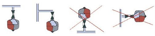
Instruction manual, installation, use and maintenance IBAIONDO (p. 6)
• Represents the entry of water to the membrane. Just water should enter.
• In the two figures on the left, no air can enter. Air is less dense than water and always occupies high points. (correct solution)
• Air enters the two figures on the right. (wrong solution)
Install cutter wrench between the expansion vessel and the installation.
• Forbidden for some time, it is totally necessary to carry out maintenance.
• If it is recommended, that once these functions have been carried out, the lever is removed from the cut-off key to avoid accidentally closing the circuit expansion.
Number and situation of the expansion vessels
1
Since the expansion vessel does not have the safety of the installation as its primary purpose, but rather its correct operation is installed in the place set in the project, preferably in the suction of the pumps.
One or more can be installed.
If in an installation it is verified that the installed expansion vessel is less than necessary, several can be installed.
Example
Suppose an installation with a 100 liter expansion tank.
The installation demands a 300 liter expansion vessel and therefore requires 200 liters more expansion.
Always on the same location, you can install the existing 100 with:
• 1 of 200
• 2 of 100
• 4 of 50
• In total between the ones that are installed and those that are installed, they must add 300, which is what the installation requires.
This indication is by way of example. It is recommended to install one.
Pathologies of the facilities related to expansion
1
In some installations, pathologies related to the expansion vessel are observed.
expansion vessel that has not been regulated
• The expansion vessel comes from the factory with an initial pressure in its calderin.
• This pressure will hardly match the one at the installation site.
• At the point where it is installed, a higher pressure or a lower pressure will be required.
• The boiler pressure data is very important and must appear in the user and maintenance manual.
• If it is higher, a nitrogen part is removed until the pressure is adjusted.
• If it is lower, air is injected until the pressure is adjusted.
What problem does an unregulated expansion vessel present?
• If the pressure of the vessel is higher, the minimum pressure of the installation is greater than that required.
• There is a smaller differential between maximum and minimum pressures, so when expanding the water can reach the regulation values of the safety valves and lose water through them.
• If you lose water, when it cools, air enters the installation.
• Continuously add water.
• If the pressure of the vessel is lower, the minimum pressure of the installation is lower than that required.
• The membrane has a greater initial volume of water, which subtracts volume of air in the vessel for expansion (the effect is from a smaller glass)
• By having a lower volume of expansion, higher pressures are reached and when reaching the regulation values of the safety valves, water comes out of them.
• When the water cools, air enters the installation.
• Continuously add water.
• It may happen that the expansion vessel is higher than necessary and is regulated below its minimum pressure.
• If the pressure of the vessel is lower, the minimum pressure of the installation is lower than that required.
• When the vessel admits a greater volume of expansion, it will not reach the maximum pressure of the safety valves.
• In that case, when the water cools down, its volume decreases and when it takes up less space, air enters the installation.
• No water is added, although the effect of air is continuously suffered.
Solution
• Adjust the minimum pressure according to what is specified in the use and maintenance manual.
• Adjust the pressure of the vessel.
• Verify that the maximum pressure is at least 0.5 bar lower than the regulation of the safety valves.
Small expansion vessel
• It has been indicated when referring to the unregulated expansion vessel.
• Not able to absorb expansion increase
• The pressure in the circuit is increased
• Loss through safety valves.
• Air inlet
• Continuous water replenishment
Solution
• Increase the expansion volume.
Membrane breakage of the expansion vessel
• It can occur and actually occurs with some frequency.
• From that moment on, it contacts the nitrogen expansion vessel or air with the water.
• The nitrogen or air contained in the boiler dissolves in the water, reducing the volume of gas. As the pressure increases, solubility increases, until it completely disappears.
• The practical effect is that each time the air or nitrogen mattress is lower, the pressure of the circuit increases and water comes out through the safety valves.
• In the end it is as if there were no expansion vessels.
• Not able to absorb expansion increase
• The pressure in the circuit is increased
• Loss through safety valves.
• Air inlet
• Continuous water replenishment
Solution
• Membrane replacement
• Filling the glass with air or nitrogen according to the value specified in the Installation Use and Maintenance Manual.
Problem with the air and water inlet in the facility
• Air intake to the installation can occur:
• If the minimum pressure is not correctly regulated and when the water cools, it occupies less volume than the total of the circuit.
• Whenever water leaks occur through the safety valves.
• The air intake is made:
• Directly through the elements in contact with the atmosphere
• With the supply water
• Air has a number of harmful effects:
• It dissolves in the water and distributed throughout the circuit.
• In the supply water there is also oxygen.
• Oxygen attacks metallic elements.
• It occupies the high points of the installation, so that if the appropriate measures have not been taken in design and execution, it requires continuous purging in the circuits.
• Water for supply also has harmful effects:
• In water other than oxygen contains mineral salts.
• An energy contribution is necessary to increase its temperature.
• Mineral salts precipitate in the heat exchange elements, reducing thermal transmissions.
• The energy efficiency and life of the installation are reduced.
expansion vessel higher than necessary.
1
In this case, it is very important to correctly regulate the minimum pressure, to avoid the pathology described above, which occurs if it is set to a lower value.
• When the expansion vessel is greater than the necessary operation of the installation is not only correct, but also improves.
• The glass is calculated so that the installation works between a minimum pressure and a maximum pressure.
• The minimum pressure is maintained.
• The maximum pressure decreases because there is a greater volume of air to compress.
• All elements will be subjected to a pressure below the maximum set in the project.
Expansion vessels in solar energy installations.
1
The operation is specified, although these expansion vessels, when working at higher temperatures, have air-water separation membranes built to withstand higher temperatures.
refrigerated expansion vessels.
1
Whenever reference is made to the expansion vessel, the idea arises that it is only necessary for installations that increase its temperature.
However, they are also necessary in refrigeration facilities.
What happens in a refrigeration circuit that is for example at 25ºC. And does the chiller start?
• At 25ºC., the water occupies the total volume of the installation.
• If the water is cooled to 7ºC, the volume of water is reduced, which causes the air to enter the circuit.
• Therefore, to avoid this contingency, it is necessary to establish an initial overpressure based on the filling temperature that maintains an overpressure for the lowest temperature in the most unfavorable conditions.
• In this case, the correct thing is to consider the temperature of 4ºC. which is where water has its maximum density.
• Everything indicated above is valid and this initial overpressure at 4ºC., can be established between 0.7 and 1 bar.
Expansion vessels in domestic hot water
1
In the production of domestic hot water, what happens in any conventional electric heater, which when the water heats up increases its volume.
In a domestic thermos a drip is produced by the safety valve installed at the inlet.
In a centralized installation to avoid these drips, it is convenient to install an expansion vessel, which works in the same way indicated for heat, with the particularity that:
• It is an expansion vessel in an open circuit that expands when the temperature increases and there is no consumption.
• The expansion vessel used in heating circuits is not valid, because it has to be built with elements approved for sanitary water.
Expansion vessels with mass transfer.
1
It is not common in hotel facilities.
It is only part of large installations, where a great expansion is required and there is little space.
This technique consists of maintaining the pressure of the installation by regulating the volume of air in the boiler by means of a compressor.
If the pressure in the installation tends to drop from the set value, air is injected into the pressure boiler.
If the pressure increases, air is expelled from the pressure boiler.
It requires a compressor, a sophisticated control system and a specific maintenance.
regulatory requirements
1
The Thermal Installations Regulation (RITE) states:
IT 1.3.4.2.4 Expansion
1. The closed water circuits or aqueous solutions will be equipped with a closed-type expansion device, which allows the volume of fluid expansion to be absorbed without giving rise to mechanical stresses.
2. The design and dimensioning of expansion systems is valid following the criteria indicated in Chapter 9 of the UNE 100155 standard.
IT 1.3.4.4.5 Measurement
6. In nominal thermal power installations greater than 70 kW, the minimum equipment of measuring devices will be as follows:
b) Expansion vessels: a manometer.
Expansion vessel maintenance
1
Preventive maintenance operations include:
Review of the expansion vessel
• When the rated useful power is greater than 70 kW.
• The review will be monthly.
As usually happens in the RITE maintenance headings, it indicates the requirement, although it does not specify the procedure to carry out this maintenance.
First of all, the maintainer should consult the manual of use and maintenance.
The data that should appear for the glass:
• Tank fill pressure.
• Minimum installation pressure.
• Temperature corresponding to the minimum pressure.
• Maximum installation pressure.
• Maximum operating temperature.
In the mandatory monthly inspection of a heat circuit it is convenient to verify:
• The handle of the cutter key of the cup is disassembled.
• It is not mandatory, if recommended to prevent anyone from accidentally closing it.
• Beak pressure gauge, mark correctly
• Operation analysis:
• To carry out fast and effective maintenance, it is convenient that the indicated data appear in the verification protocol.
• With this data, if the installation is in service, and the pressures are within the fixed ranges, it would not be necessary in the monthly test to isolate the glass and verify the pressure of the boiler, because during that time the installation is left without expansion.
• Appearance of the glass:
• Visual inspection.
The Maintenance Technical Guide recommends that pressure checking is performed twice a year.
It is also recommended by the Ibaiondo manual.
Indicate that the technical guidelines are recommendations and not mandatory.
• Exterior cleaning
• Oxidations and corrosion
• Manometer check
• Membrane state
• Checking the pressure in the expansion chamber.
Calculation of the expansion vessel
1
In the Technical Guide for Water HVAC, section 3.1.3 pp. 39 to 41 The calculation procedure is developed.
There are also software from manufacturers that offer the selection of the most suitable vessels.
The data necessary for the calculation are:
• The volume of water contained in the circuit.
• The position of the vessel with respect to the circuit.
• If it is at the highest point, the lowest or an intermediate point.
• This pressure corresponds to the gauge height.
• The relative position of the glass with respect to the pumping equipment.
• If it is in the aspiration, in the drive or in a middle zone of the circuit.
• This pressure corresponds to the overpressure that the pumping equipment can provide.
• If it is in the aspiration, the value with respect to pumping equipment is 0.
• The overpressure that must be increased.
• Recommended from 0.7 to 1 bar.
• The minimum temperature estimated in the circuit.
• Even if it is greater than 4ºC., if it is calculated at this temperature, it is on the safety side.
• The maximum temperature that the circuit will reach.
• The maximum working pressure in the circuit.
• Logically, this pressure must be lower than the elements and equipment installed and the safety valves.
• Must be at least 0.5 bar lower than safety valves.
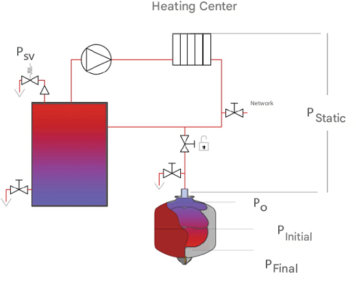
Instruction, Installation, Use and Maintenance Manual (p. 4)
• The static pressure corresponds to the initial gauge pressure
• At this pressure, at least 0.5 bar should be increased.
• The influence of the pump must be analyzed at the point where the glass is.
• The minimum pressure will be
• Static pressure
• Pressure due to the influence of the pump
• Overpressure 0.5 bar
• The filling pressure of the beaker or inflation pressure will be:
• Minimum pressure – (0.2, or 0.3) bar
• This ensures that at the minimum pressure there is a small volume of water in the glass.
• The maximum pressure or final pressure is lower than that of safety valves.
• It is recommended at least 0.5 bar with respect to the valve set.
Conclusions.
The allowable expansion vessels in thermal installations are closed expansion vessels.
The mission of the expansion vessel is to absorb the dilations that occur in the water caused by heat.
They must appear in the Hotel Use and Maintenance Manual specifying the minimum and maximum pressures, as well as the initial air pressure in the glass, for which it has been calculated and the temperatures corresponding to these pressures.
The expansion of the water exerts pressures on the circuit that must be less than the allowable by the elements and those regulated in the safety valves.
• It is recommended at least 0.5 bar lower than the safety valves.
When the water cools and its volume decreases, it is necessary to maintain an overpressure in the circuit to prevent air from entering.
• It is recommended at least 0.7 to 1 bar above the minimum.
The expansion vessel is the reference point of the installation and it is advisable to install it in the pump suction.
In the assembly of the expansion tank, the entry of air into the membrane where the water is housed must be avoided.
One or more expansion vessels can be installed in the installation, although it is convenient that they are all located in the same location. (Recommended is 1)
In the facilities, various pathologies are observed that generally come from the lack of knowledge that the maintainer has in relation to the maximum and minimum pressures at which the glass must be regulated at the site. It is a fact that has to appear in the user and maintenance manual.
• Minimum pressure
• Vessel filling pressure
• Maximum pressure
• If the pressure in the boiler is higher than the minimum necessary, the installation works overpressured and water will come out of the safety valves.
• If the pressure in the boiler is lower than that required, the volume of air to absorb the compression is reduced, the effect is as if the glass were small, there is not enough air mattress to absorb the expansion, causing the water to escape through the safety valves.
• If the pressure in the boiler is lower than the necessary one and the glass is oversized, air inlet occurs when the water cools.
• If the vessel is greater than required and the air pressure in the boiler is correct, the installation is subjected to a lower pressure, which can be considered as an improvement.
• Membrane break. Air in water is dissolved, the installation is left without expansion and the overpressure causes the water to escape through the safety valves.
• Whenever there is water outlet through safety valves, water and air enter the installation, causing poor operation in the installations, increasing energy consumption and shortening its useful life
In refrigeration installations, expansion vessels are also necessary, although in this case the minimum pressure occurs during the operation of the chiller when the mass of water occupies a smaller volume.
In domestic hot water, expansion vessels are installed to absorb water expansion at times when there is no consumption, although the vessels used in heating are not admissible in this installation and must be specific for domestic hot water.
For proper maintenance, the maintainer must know the pressure range at which the vessel works and the filling pressure. In this way, with a simple ocular inspection, it detects if the operation is correct and in the most specific revisions, repositions of membranes and substitutions adjust to the values set in the project.
We Resolve has corrected numerous pathologies related to the expansion vessels that have contributed to the improvement of the operation of the installations, reducing energy consumption, optimizing the maintenance functions caused by the pathologies, limiting the number of breakdowns and increasing the useful life of generators, receivers and equipment.
Correct maintenance requires the proper training of technicians, the investigation of pathologies, the development of procedures, optimizing existing resources and the innovation of techniques that allow to solve pathologies, minimally affecting the existing facility (R+D+i) research, development and innovation, applicable to all maintenance.
Literature.
1
Rite 2007 comments
Technical guide Water air conditioning installations
Technical Guide Maintenance of Thermal Installations
IBAIONDO Expansion vessels Fixed membrane CMF
https://www.ibaiondo.com/wp-content/uploads/sites/250/2019/08/manual-instructions-cmf.pdf
21/08/2024
José Arroyo Martín
Ingeniero Tecnico Industrial en Electricidad y Mecánica